Overall clarifier volume from the largest to the smallest designs can fluctuate as much as 150 or more. The main reason for this is a lack of understanding of what pollutants primary clarifiers are capable of removing.
2
This tool is useful in determining the dimensions of a rectangular clarifier.
. For example it is not uncommon to see in many wastewater treatment plant master or facilities plans a statement such as The primary. Clarifiers also referenced as sedimentation tanks or settlers are an inte gral part of ever y. The bars are 10 mm thick and openings are 3 cm wide.
Design of primary clarifiers has historically been done more empirically than rationally. For example when primary sludge is drawn from clarifiers it is sometimes by gravity and sometimes by direct suction using pumps. 6 These design parameters may change slightly based on site-specific conditions.
11 - Settled sludge specific gravity 102. The target capture velocity is 02 mms. 3 - Influent VSS 150 mgL.
Circular primary clarifiers are used to separate suspended solids from a liquid. 952000 21623 PM. Monroe Environmentals Primary Circular Clarifiers are designed to receive raw wastewater after it has been pre-screened to remove large objects and grit.
A circular clarifier has a diameter of 150 ft. In meeting this objective emphasis is placed on understanding primary clarifier performance focusing on the process objective of primary clarifiers and. Fongers Dave DEQ Created Date.
However anticipated BOD removal for wastewater containing high quantities of industrial wastewater should. Primary clarifier sizing shall be calculated for both flow conditions and the larger surface area derived shall be utilized. Use the following design criteria and constraints.
A properly designed primary clarifier should remove 30 to 35 of the influent BOD. They also have similar configurations and designs. But other design variables are all over the map.
To remove 10 solids from water using sedimentation. Steel shells and tanks are also available. 10 - Concentration of settled sludge 8000 mgL.
The velocity between bars 3. Example 7-7 Design a clarifier -thickener for the pulp and paper wastewater using the testing data described in Figures 7-84 through 7-95 to accommodate an influent. Guideline and Manual for Planning and Design in Japan JSWA 2009 62 HYDRAULICS OF SLUDGE PIPELINES 621 Sludge Piping Sludge piping can be by gravity or by pumping.
In addition to the above-mentioned there are other practical design criteria of primary settling for example. Relatively small inlet pipe and slots potential floc shear Mixed liquor fed at top of tank potential waterfall effect Impinging exits and submerged flocwell are steps in the right direction. Primary Clarifier Design Calculation The clarifiers are used in water and wastewater treatment process to remove suspended solids from water under the sole influence of gravity.
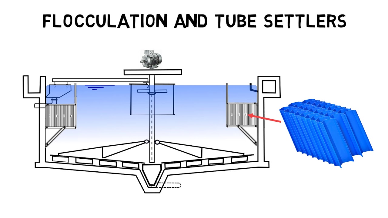
Water Environment Federation Improving Water Quality for 75 Years Founded in 1928 the Water Environment Federation WEF is a not-for-profit technical and. They are used extensively in the waste water treatment and water treatment industries but also in mining facilities reverse osmosis plants and paper and pulp plants to name a few industries. The tube settler above the floc hopper needs to be 72 cm long.
The objective of the primary clarifier chapter in WEFs new Clarifier Manual of Practice is to move away from empiricism and towards something more rational and at the same time practical. 12 - 60 of reactor volume will be decanted each day. The angles and configurations of the plates are vastly different from manufacturer to manufacturer.
The cross section of the channel and the dimension needed 2. If 180 mgL suspended solids is removed by the primary clarifier how many lbday suspended solids will be removed when the flow is. The most widely used clarifiers are.
Bar Screen Design Example A manual bar screen is to be used in an approach channel with a maximum velocity of 064 ms and a design flow of 300 Ls. The tube settler diameter is 254 cm. The objective of the primary clarifier chapter in WEFs updated Clarifier Design Manual is.
The vertical section of the clarifier v z f has a net upflow velocity of 3 mms. Plate spacing will vary from 34 to 2 and more. The head loss in meters 4.
The most important sizing parameters in the primary clarifiers design are. Clarifiers are the principle mechanisms for solidliquid separation in primary intermediate intermediate and final wastewater clarification applications. 2 - Influent suspended solids 200 mgL.
Because the process objective is more appropriately focused on the clarified liquid rather than the thickened underflow the unit operation discussed herein is referred to as primary clarification and the units themselves as primary clarifiers. 8 9 Primary and secondary clarifiers essentially share the same primary function. This velocity is maintained in the tube settler v α.
Clarifier Calculations Last modified by. Solve for the length of the tube settler. The clarifiers are used in water and wastewater treatment process to remove suspended solids from water under the sole influence of gravity.
Primary Clarifier Design Calculation. Conventional inlet design in America January 27 2016 10 NEWEA Optimizing Clarifier PerformanceAre We Designing the Clarifiers Right. SPS Engineering manufactures many types of clarifier mechanisms to best suit the clarification process.
We will 7 examine these parameters in greater detail later in the chapter. This primary wastewater treatment sedimentation tank will produce a homogeneous liquid capable of being treated biologically and a sludge that can be separately treated or. Clarifiers form part of the process known as sedimentation.
The central baffle in a circular clarifier with central feed normally has. Arial Times New Roman Symbol default 1_Default Design 2_Default Design 3_Default Design 4_Default Design 5_Default Design 6_Default Design 7_Default Design 8_Default Design 9_Default Design 10_Default Design 11_Default Design 12. Normally weir overflow rates of 10000 to 20000 gpdft 2 are used in the design of a settling tank.
The weir overflow rate can be determined by. 1 - Influent flow-rate 3800 m3day. These treatment facilities are used to remove solids.
Clarifier Basics How Do Clarifiers Work I Clarifier Design Youtube
2
2
2

Schematic Illustration Of A Clarifier As Usually Employed After A Download Scientific Diagram
Wastewater Clarifier Performance

State Point Analysis Clarifier Design Rules Youtube

How To Design Clarifier For Primary Treatment Of Water Treatment Plant
0 comments
Post a Comment